The Working Principle of Extruders
In the material molding processes of industrial production, extruders have become critical equipment across industries such as plastics, rubber, food, and building materials, leveraging their core advantages of continuous operation and high precision. Understanding an extruder’s operating principles is a core prerequisite for achieving efficient equipment performance, optimizing production processes, and enhancing product quality—it not only enables technicians to precisely control production parameters but also empowers procurement and maintenance personnel to make more scientific decisions regarding equipment selection, troubleshooting, and routine maintenance. For industrial enterprises pursuing production stability and cost control, systematically mastering extruder operating principles serves as a crucial foundation for boosting core production competitiveness.
Understanding How Extruders Work
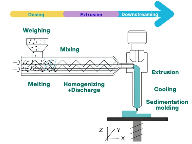
The core operating principle of an extruder is “converting solid materials into continuous formed articles through physical processes.” The overall workflow can be summarized into six key stages: “Raw Material Pretreatment → Feeding → Conveying & Compression → Plasticization & Melting → Extrusion Molding → Cooling & Shaping.” Each stage works closely together to ensure a smooth transition of materials from solid pellets to finished products, with detailed breakdowns as follows:
1.Raw Material Pretreatment (Preparatory Stage)
While not directly part of the extruder’s internal workflow, this stage is critical to subsequent operational stability. Different materials require targeted pretreatment: for example, plastic pellets need moisture removal via drying equipment (to prevent defects like bubbles and silver streaks in finished products), rubber raw materials require pre-mastication and softening, and food ingredients need crushing and uniform mixing. Pretreated materials must meet the requirements of “appropriate fluidity, impurity removal, and uniform composition” to lay the foundation for the subsequent plasticization and melting stage.
2.Feeding Stage
Pretreated materials enter the barrel through the hopper at the top of the extruder. A feed screw or feeding device is typically installed below the hopper to achieve uniform and quantitative material conveyance. High-quality extruders are equipped with level sensors and variable frequency drives (VFDs) in their feeding systems, which dynamically adjust the feeding speed based on the material volume inside the barrel. This prevents barrel overload from excessive feeding or production fluctuations due to insufficient feeding, ensuring the continuity of the entire workflow.
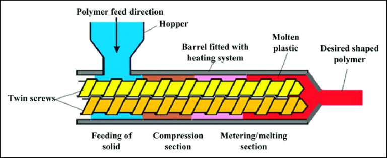
3.Conveying & Compression Stage
After entering the barrel, materials are conveyed toward the machine head by the thrust of spiral blades as the screw rotates at high speed. The core of this stage is “compression”: the screw pitch gradually decreases from the feeding zone to the plasticizing zone, and the clearance between the barrel inner wall and the screw is minimal. As the screw rotates, materials are continuously compressed, internal air is expelled (to avoid air bubbles after melting), and materials are initially heated by shear force, preparing for subsequent plasticization and melting. The efficiency of conveying and compression directly depends on the screw’s spiral structure, rotational speed, and barrel temperature settings.
4.Plasticization & Melting Stage (Core Critical Stage)
This is the central link in the extruder’s operating principle, aiming to convert solid materials into a uniform molten state. During conveying and compression, materials are heated by two heat sources simultaneously: external heat from heating devices outside the barrel (such as electric heating coils and hot oil jackets) and internal shear heat generated by friction between the rotating screw and materials, as well as between materials and the barrel inner wall. These dual heat sources work synergistically to gradually raise the material temperature to the plasticization point, causing solid pellets to soften and melt, ultimately forming a uniform, continuous molten material. The key to this stage is “temperature uniformity”—excessively high temperatures can cause material degradation, while insufficient temperatures lead to incomplete plasticization, both of which compromise finished product quality.
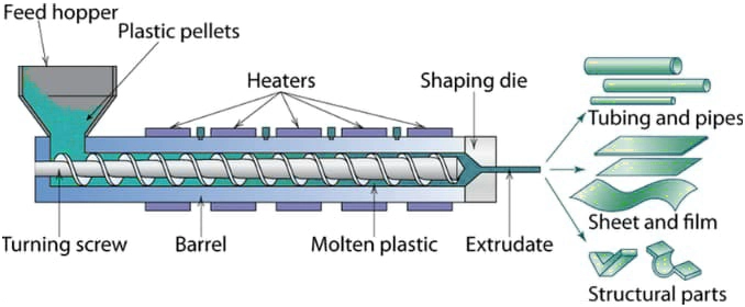
5.Extrusion Molding Stage
Uniformly molten materials are pushed by the screw’s continuous thrust through the machine head at the end of the barrel and into a custom die. The machine head converts the spiral flow direction of the molten material into linear motion while further compacting the material; the die’s internal cavity shape directly determines the cross-sectional profile of the finished product (e.g., pipes, sheets, profiles, films). Dies typically include flow distribution devices and compression zones to ensure uniform material distribution, preventing defects like uneven wall thickness and dimensional deviations in finished products.
6.Cooling & Shaping Stage
Molten products extruded from the die are at high temperatures and require immediate cooling and solidification via cooling equipment to fix their shape and dimensions. Common cooling methods include water cooling (water tanks, spray cooling) and air cooling (air rings, hot air cooling), with the choice depending on the product material and shape: water cooling is widely used for pipes and profiles, while air cooling is preferred for films and wires. Cooling speed must be carefully controlled—excessively fast cooling can induce internal stress, leading to cracking and deformation, while slow cooling reduces production efficiency and may cause unstable product dimensions. After cooling and shaping, the products are pulled by a puller and cut by a cutter to obtain finished products that meet specifications.
Differences in Operating Principles Among Different Types of Extruders
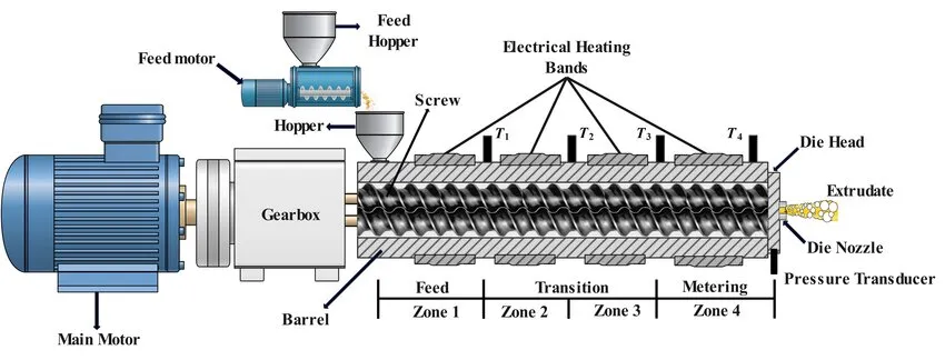
Extruders are primarily classified by “number of screws” (single-screw, twin-screw, multi-screw). While all types share the same core operating logic, they exhibit significant differences in key processes such as conveying, plasticization, and melting, resulting in varying material and application suitability. Specific differences are as follows:
1.Single-Screw Extruders: Friction-Driven Conveying for Commodity Materials
The core operating principle of single-screw extruders is “friction-based conveying”—material transport within the barrel relies primarily on frictional differences between the material and the barrel inner wall, as well as between the material and the screw surface. The screw typically features a three-section structure: feed section (for material conveying), compression section (for compaction and preliminary plasticization), and metering section (for uniform plasticization and quantitative delivery).
Advantages: Simple structure, easy operation, and low maintenance costs.
Disadvantages: Low plasticization efficiency and limited material adaptability. Primarily suitable for commodity plastics such as polyethylene (PE) and polypropylene (PP), as well as low-processing-difficulty materials. Ideal for producing conventional products like pipes, films, and wire coating.
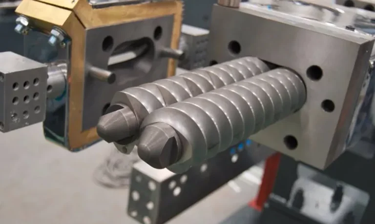
2.Twin-Screw Extruders: Intermeshing Conveying for Complex Materials
Twin-screw extruders operate on the principle of “positive displacement intermeshing conveying”—two intermeshing screws rotate to force materials forward through the engagement of spiral blades, eliminating reliance on material-barrel friction. Based on rotation direction, they are categorized into co-rotating twin-screws (e.g., parallel co-rotating) and counter-rotating twin-screws (e.g., conical counter-rotating):
- Co-rotating twin-screws offer superior mixing uniformity and higher plasticization efficiency.
- Counter-rotating twin-screws generate greater extrusion force, suitable for high-viscosity material processing.
Advantages: High conveying efficiency, excellent plasticization uniformity, and capability to process complex materials (e.g., PVC, modified plastics, filled plastics) with high viscosity or high filler content.
Disadvantages: Complex structure, high manufacturing costs, and demanding maintenance. Suitable for producing high-value-added products such as specialty profiles, composite pipes, and modified plastic pellets.
3.Multi-Screw Extruders: Precision Intermeshing for Specialty Materials
Multi-screw extruders (triple-screw, quadruple-screw, etc.) leverage “high-precision intermeshing conveying with multiple screws.” Through the coordinated rotation of three or more screws, they achieve extreme mixing uniformity, high-efficiency plasticization, and precise material delivery. Their core advantages include “ultra-high plasticization efficiency, short material residence time, and precise temperature control,” effectively preventing material degradation.
Ideal for processing heat-sensitive, high-performance specialty materials (e.g., biodegradable plastics, high-performance engineering plastics, nanocomposites). Due to their complex structure and high cost, multi-screw extruders have limited market applications, primarily serving high-end specialty material processing scenarios such as aerospace-grade engineering plastics and medical high-end consumables.
Key Components of an Extruder
The realization of an extruder’s operating principle relies on the collaborative coordination of its core components. Each component performs a critical function, and their performance directly impacts the extruder’s efficiency, molding quality, and operational stability. The core components and their functions are as follows:
1.Screw: The “Core Power Component” of the Extruder
As the primary component determining an extruder’s performance, the screw is directly responsible for material conveying, compression, plasticization, and melting. Key parameters include the length-to-diameter (L/D) ratio (affecting plasticization efficiency), thread pitch (determining conveying speed), and helix angle (influencing conveying capacity). Based on processing requirements, screws are classified into gradual compression (suitable for crystalline plastics), abrupt compression (suitable for amorphous plastics), and barrier-type (enhancing plasticization uniformity) designs. Constructed from wear-resistant, high-temperature-resistant alloy steel (e.g., 38CrMoAlA), screws undergo nitriding treatment to improve surface hardness.
2.Barrel: The “Closed Processing Chamber” for Materials
Working in tandem with the screw, the barrel forms a closed processing chamber that provides space for material conveying, compression, and plasticization. Its inner wall is typically equipped with a wear-resistant bushing to prevent material-induced abrasion. Externally, heating and cooling devices (e.g., cooling channels, cooling fans) are attached to achieve precise segmental temperature control. The barrel material must match the screw, requiring high temperature resistance, wear resistance, and corrosion resistance to ensure long-term stable operation.
3.Hopper and Feeding Device: The “Material Inlet”
The hopper stores raw materials, usually made of stainless steel with a smooth inner wall to avoid material residue. Hoppers for large extruders are equipped with agitators to prevent material caking. Installed below the hopper, the feeding device (e.g., feed screw, vibratory feeder) delivers raw materials to the barrel at a uniform rate. Its speed is adjustable via a variable frequency drive (VFD) to match the screw’s conveying capacity, preventing material accumulation or interruption.
4.Machine Head and Die: The “Shape-Defining Components” for Finished Products
The machine head acts as a transition component connecting the barrel and die. Equipped with internal structures such as a spider and compression zone, it streamlines material flow, compacts materials, and ensures uniform distribution into the die. The die is a customized component with an internal cavity designed to match the finished product’s shape. Common types include pipe dies, sheet dies, profile dies, and film blowing dies. The precision of the machine head and die directly determines the finished product’s dimensional accuracy and surface quality, requiring high-precision machining processes.
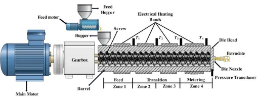
5.Drive System: The Core of Power Output
Composed of a motor, reducer, and coupling, the drive system provides stable power for screw rotation. The motor is typically a variable frequency motor, enabling precise adjustment of screw speed (directly affecting conveying speed and production capacity). The reducer reduces motor speed and increases torque to ensure sufficient rotational power for the screw. The coupling connects the motor to the reducer and the reducer to the screw, transmitting power while compensating for installation deviations.
6.Temperature Control System: The “Guarantee Component” for Plasticization Quality
Consisting of heating devices, cooling units, temperature sensors, and controllers, the temperature control system maintains the temperature of the barrel, machine head, and die within preset ranges. Heating devices supply external heat for material plasticization, while cooling units regulate overheated areas (e.g., excessive temperature in the plasticization zone). Temperature sensors real-time collect data and feed it back to the controller, enabling closed-loop automatic temperature control. This ensures uniform material plasticization and prevents temperature fluctuations from compromising finished product quality.