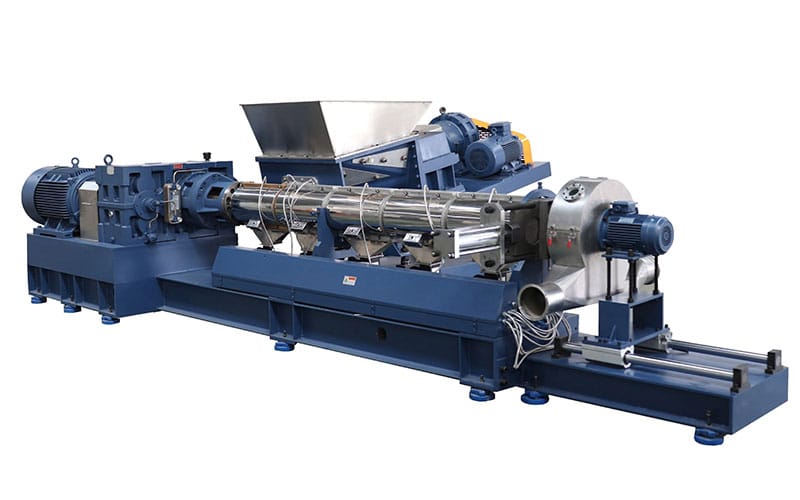
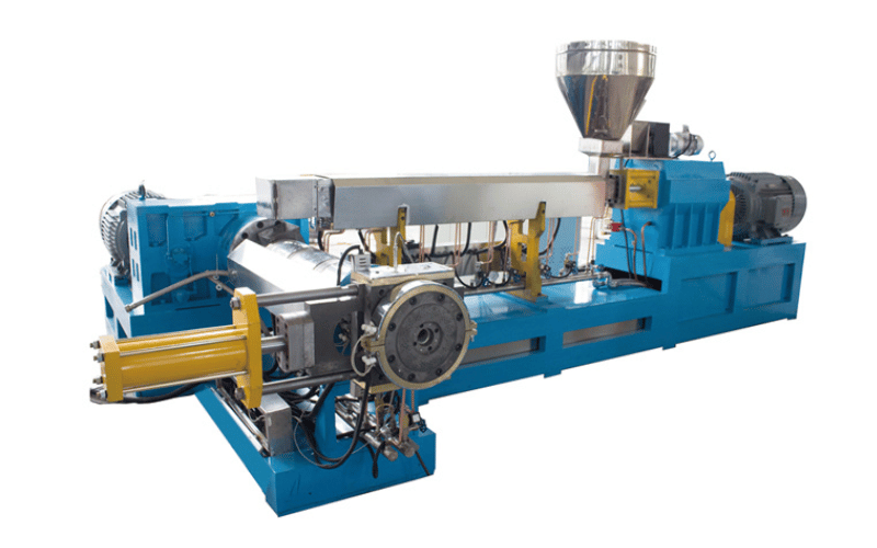
Single-screw extruders are the “basic model” equipment in plastic processing. From ordinary PE pipes to PVC wire insulation, many common plastic products rely on them for production. Their structure is simpler than twin-screw extruders, but the performance of core components directly impacts production efficiency and finished product quality—for example, screw wear can cause uneven plasticization, while inaccurate temperature control can lead to material decomposition. First, we’ll disassemble key components for clarity, then explain the working principle and applications to help you grasp its “operational logic.”
Main Components of a Single-Screw Extruder
1. Barrel
The barrel serves as the “outer shell” of the single screw. Typically made from 38CrMoAlA alloy steel, its inner wall undergoes nitriding treatment (achieving a hardness of HV850 or higher), providing wear resistance and corrosion protection suitable for prolonged contact with molten plastic. Its core design features “sectioned heating,” usually divided into 3-5 zones (corresponding to feed, compression, and metering sections). Each zone has an independent heating ring (often cast aluminum for rapid heating), enabling precise temperature control across different areas (e.g., PE processing requires 140-150°C in the feed section and 170-180°C in the metering section).
Some barrels feature insulation layers around the heating elements to minimize heat loss. The end near the mold is flanged for easy mold installation and removal, simplifying cleaning or specification changes for small-to-medium factories.
2. Screw
The screw is the “heart” of a single-screw extruder, typically made of nitrided steel or bimetallic alloy (the latter preferred for high-filler processing). It features a “three-section” structure with distinct functions for each section:
Feed Section: Features the deepest screw grooves (typically 3-8mm, depending on screw diameter). Its role is to “receive and feed material”—consistently pushing pellets/powder from the hopper forward while preventing bridging (material blockage at the feed inlet).
Compression Section: Screw grooves gradually shallow from deep to shallow. Through rotational shear force and barrel heating, solid material is compacted and melted, completing the “solid → melt” transformation.
Metering Section: Features the shallowest screw grooves, serving to “uniform material and stabilize pressure”—stirring the melted material evenly and pushing it toward the mold at a steady pressure to ensure consistent extrusion volume.
Different materials require different screw designs. For example, PVC uses a “step-type screw” (short compression section to prevent decomposition), while PE uses a “gradient-type screw” (for gentle plasticization).
3. Feeding System
The feeding system primarily consists of a hopper and feeder, with the core function being “quantitative feeding”—irregular feed rates cause uneven product thickness. Hoppers are typically stainless steel with capacities ranging from 50-200L (depending on production capacity), some equipped with agitators to prevent powder clumping. Feeders are mostly “volumetric feeders” (common in small-to-medium factories), conveying material via screws or belts. They allow manual speed adjustment with precision sufficient for standard processing (error within ±3%).
For processing materials with high moisture content (e.g., recycled PP), the hopper can be equipped with a hot-air drying unit to pre-dry moisture and prevent bubbles in the finished product.
4. Drive System
The drive system comprises a variable-frequency motor, gear reducer, and coupling, providing stable rotational speed and torque to the screw. The variable-frequency motor adjusts speed (typically 10-300 rpm); higher speeds increase extrusion volume (but must match plasticizing capacity to ensure complete melt fusion). The gearbox’s core function is “speed reduction and torque increase”—motors offer high speed but low torque. The gearbox reduces speed while boosting torque, enabling the screw to effectively push high-viscosity materials (e.g., PVC melt). The coupling connects the motor and screw, absorbing vibrations to prevent screw bending from uneven forces.
5. Temperature Control System
The temperature control system comprises heating elements, cooling fans/water jackets, and temperature controllers, with the core objective being “preventing temperature deviations.” Heating elements raise barrel temperatures, with each section independently controlled. For example, when processing PVC: the feed section must not overheat (to prevent premature melting and sticking to the barrel walls), while the compression section requires elevated temperatures (to ensure complete melting). If any section exceeds its set temperature, the cooling fan (or water jacket) activates to lower the temperature, preventing material decomposition (e.g., PVC turning black above 200°C).
Temperature controllers are typically digital displays, showing real-time temperatures for each section with ±1°C accuracy. They are simple to operate, allowing even beginners to master them quickly.
6. Die
The die serves as the “terminal component” of a single-screw extruder. Material melt flows through the die’s channels to extrude specific shapes. Constructed from Cr12MoV die steel with a polished surface (roughness Ra ≤ 0.8μm), it minimizes material adhesion to the walls. Structurally divided into “core” and “cavity,” the core sits centrally (featuring a cavity for conductor or support elements, e.g., wire insulation extrusion), while the cavity surrounds it externally. The gap between them defines the finished product’s thickness (e.g., PE pipe molds with 1-5mm gaps determine wall thickness).
Common molds include pipe molds, sheet molds, and wire insulation molds. Changing the mold allows production of different products, offering high adaptability.
7. Traction and Winding Devices
The traction device is typically a “track-type traction machine.” It uses two rubber tracks to grip the extruded product and pull it out at a steady speed—this speed must match the extrusion rate. Too fast will thin the product (e.g., reducing wire insulation thickness), while too slow will cause material to pile up at the die outlet. The take-up device is essentially a motorized reel that neatly winds the pulled product (e.g., PE pipe, electrical wire). Some incorporate tension controllers to prevent deformation from excessive pulling.
For instance, when producing PVC electrical wire, precise traction speed is crucial. Otherwise, the insulation layer thickness may fail to meet specifications and pass inspection.
Working Principle of Single-Screw Extruders
The operational flow of a single-screw extruder is a “continuous process from feeding to shaping,” comprising four steps where all components work in concert:
Feeding: Raw materials (pellets/powder) from the hopper enter the feeding system. The feeder conveys the material to the feed section of the barrel at a preset speed. The deep screw grooves in the feed section securely grip the material and transport it forward.
Plasticizing: As the screw rotates into the compression section, the screw grooves become shallower. Combined with barrel heating, the material undergoes compression and shearing, gradually transforming from a solid state into a uniform melt. The temperature control system must maintain precise regulation during this stage to ensure complete melting without decomposition.
Metering Extrusion: The melt enters the screw’s metering section. With shallow screw grooves and stable screw rotation, the melt is thoroughly mixed before being pushed toward the die at constant pressure. The melt passes through the gap between the die core and die sleeve, extruding the desired shape (e.g., pipe, insulation layer).
Forming and Winding: The extruded semi-finished product is pulled out at a steady speed by the traction device while being cooled (e.g., PE pipes passing through a water cooling tank) to set its shape. Finally, the winding device coils the finished product. This entire process is continuous and can operate 24 hours a day.
Applications of Single-Screw Extruders
Single-screw extruders offer the advantages of “simple structure, low cost, and easy operation,” making them suitable for processing “common, single-component” plastics. They are primarily used in three major fields:
General-purpose plastic pipes/profiles: This is the primary application, such as producing PE water supply pipes (for home installations and municipal use), PVC drainage pipes, and PPR hot water pipes. Single-screw extruders ensure stable extrusion with uniform wall thickness, meeting everyday requirements. Most small-to-medium pipe manufacturers rely on this technology.
Wire and Cable Insulation: Used for producing insulation layers on low-voltage wires (e.g., residential BV wires). PVC or PE melt is extruded over copper wires to form insulation. Single-screw machines offer simple operation and high output capacity (thousands of meters per day), making them common in wire factories.
Packaging and simple products: Examples include PE film (for food packaging), PP strapping tape, and plastic welding rods. These products have low mixing requirements, and the plasticizing capability of a single-screw extruder is fully sufficient. Additionally, the equipment cost is low (more than half the price of a twin-screw extruder), making it the preferred choice for small workshops or startups.
However, single-screw extruders have limited mixing capability and are unsuitable for high-filler compounds (e.g., glass-fiber reinforced plastics) or multi-component blends. Such applications require twin-screw extruders.